MySQL Workbench Manual In Creating a Model
This section provides a tutorial introduction to MySQL models by showing you how to create a new database model, and how to forward engineer a model to a live MySQL server.
Note
Alternatively, you can create a model from a database by using the reverse engineering wizard. For additional information, see Section 9.4.2.2, “Reverse Engineering a Live Database”.
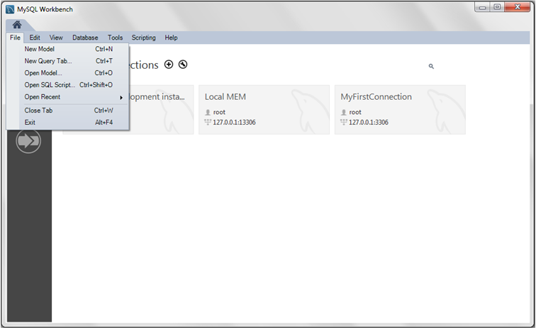
- Start MySQL Workbench. On the home screen, click the [+] icon next to theModels section on the bottom of the page, or select , . A model can contain multiple schemata. Note that when you create a new model, it contains the
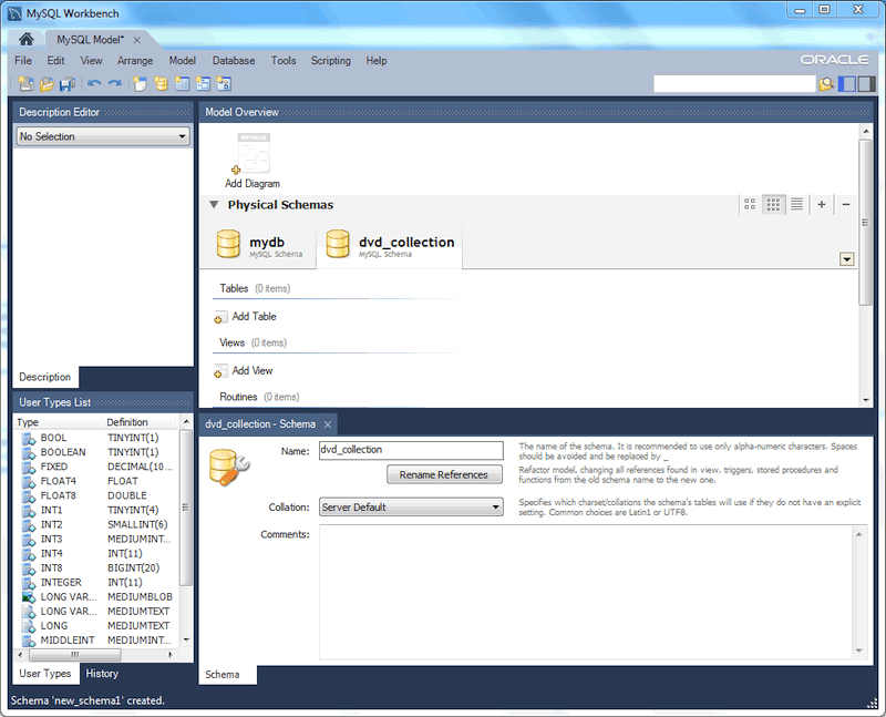
mydbschema by default. You can change the name of this schema to serve your own purposes, or delete it. - Click the button on the right side of the Physical Schemata toolbar to add a new schema. The default schema name is "new_schema1", now change it to “dvd_collection” by modifying its Name field. Confirm this change in thePhysical Schemata panel. Now you are ready to add a table.
- Double-click Add Table in the Physical Schemata section.
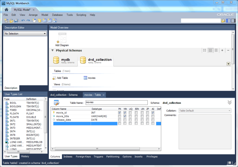
- This automatically loads the table editor with the default table name table1. Edit its Table Name field and change the table name from “table1” to “movies”.
- Next, add columns to your table. Double-click a Column Name cell, and the first field defaults to “moviesid” because (by default) MySQL Workbench appends “id” to the table name for the initial field. Change “moviesid” to “movie_id” and keep the Datatype as
INT, and also select the PK (PRIMARY KEY), NN (NOT NULL), and AI (AUTO_INCREMENT) check boxes. - Add two additional columns using the same method as described above:
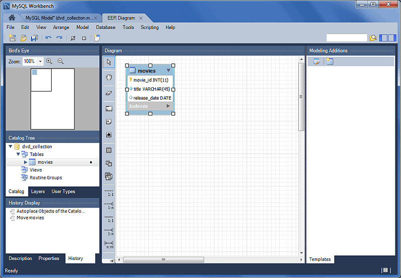
Column Name Data Type Column Properties movie_title VARCHAR(45) NN release_date DATE (YYYY-MM-DD) None - For a visual representation (EER diagram) of this schema, select , to create the EER Diagram for the model.
- In the table editor, change the name of the column “movie_title” to “title”. Note that the EER Diagram is automatically updated to reflect this change.NoteTo open the table editor, either change back to theMySQL Model tab and right-click on the
moviestable, or right-click onmoviesin the EER diagram and select an option. - Save the model by choosing , from the main menu, or click on the toolbar. Enter a model name at the file prompt. For this tutorial, enter “Home_Media” and then the model.
- Before synchronizing your new model with the live MySQL server, confirm that you already created a MySQL connection. This tutorial assumes you followed the previous Section 5.2, “Creating A New MySQL Connection (Tutorial)” tutorial to create a MySQL connection named MyFirstConnection, although an alternative connection can also work.
- Now forward engineer your model to the live MySQL server. Select, from the main menu to open the Forward Engineer to Database wizard.
- The Connection Options page selects the MySQL connection and optionally sets additional options for the selected MySQL connection. We do not require connection changes so click .NoteYou may decided to choose a different MySQL connection here, but this tutorial uses MyFirstConnection.
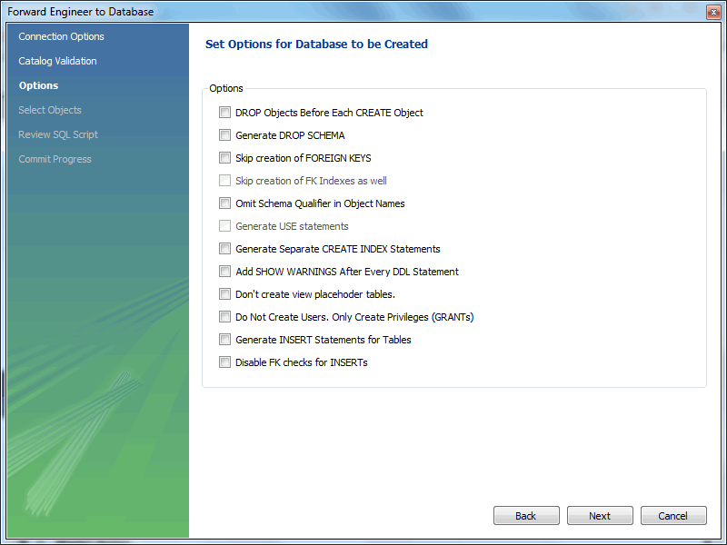
- The Options page lists optional advanced options. For this tutorial, you can ignore these and click Next.
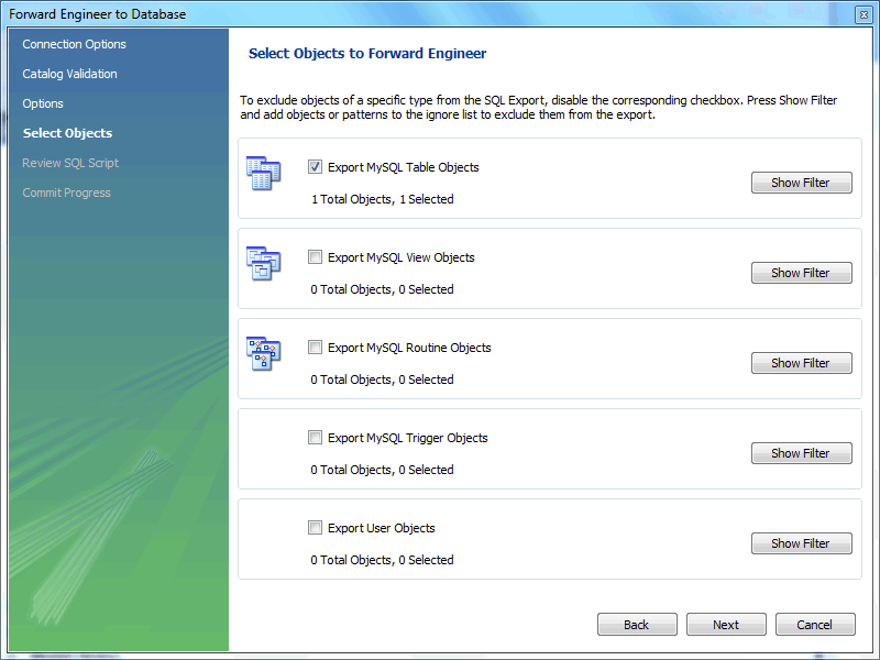
- Select an object to export to the live MySQL server. In this case, we only have one table (dvd_collection), so select
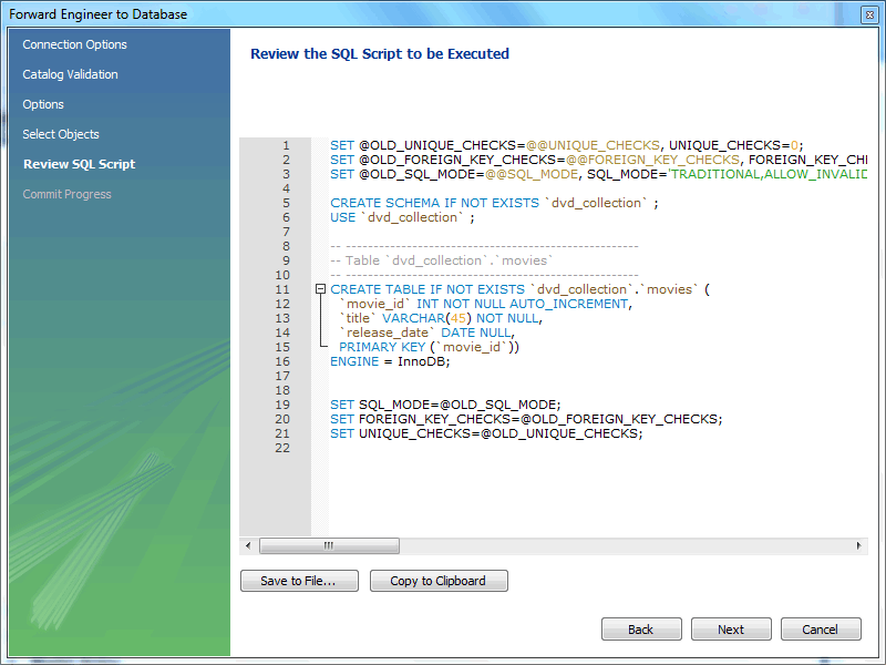
dvd_collectionand click . - The Review SQL Script page displays the SQL script that will be executed on the live server to create your schema. Review the script to make sure that you understand the operations that will be carried out.Click to execute the Forward Engineering process.
- The Commit Progress page confirms that each step was executed. Click to view the logs. If no errors are present, click to close the wizard.
- The new
dvd_collectiondatabase is now present on the MySQL server. Confirm this by opening the MySQL connection and viewing the schema list, or by executingSHOW DATABASESfrom the MySQL Command Line Client (mysql). - Ensure that your model is saved. Click Save Model to Current File on the main toolbar.
For additional information about data modeling, see Chapter 9, Database Design and Modeling.
Basic Modeling:-
Adding a Table
-
The tools in the vertical toolbar on the left of the EER Diagram tab are used for designing an EER diagram. Start by creating a table using the table tool. The table tool is the rectangular grid in the middle of the vertical toolbar. Mousing over it shows the message,
Place a New Table (T).
Clicking this tool changes the mouse pointer to a hand with a rectangular grid. Create a table on the canvas by clicking anywhere on the EER Diagram grid.
Right-click the table and choose from the pop-up menu. This opens the table editor, docked at the bottom of the application.
The table name defaults to table1. Change the name by entering invoice into the Name: field. Changes here affect the name of the tab in the table editor and the name of the table on the canvas.
Pressing Tab or Enter while the cursor is in the table name field selects theColumns tab of the table editor and creates a default column named idinvoice.
Pressing Tab or Enter again sets the focus on the Datatype list with INT selected. Notice that a field has been added to the table on the EER canvas.
Pressing Tab yet again and the focus shifts to adding a second column. Add a Description and a Customer_id column. When you are finished, close the table editor, by clicking the button on the top left of the table editor.
-
Creating a Foreign Key
Select the table tool again and place another table on the canvas. Name this table
invoice_item. Next click the 1:n Non-Identifying Relationship tool.
First, click the invoice_item table; notice that a red border indicates that this table is selected. Next, click the invoice table. This creates a foreign key in the invoice_item table, the table on the “many” side of the relationship. This relationship between the two tables is shown graphically in crow's foot notation.
Revert to the default mouse pointer by clicking the arrow at the top of the vertical toolbar. Click on the invoice_item table and select the Foreign keys tab.
Click the Foreign key Name field. The referenced table should show in the Referenced Table column and the appropriate column in the Referenced Column column.
To delete the relationship between two tables, click the line joining the tables and then press Control+Delete.
Experiment with the other tools on the vertical toolbar. Delete a relationship by selecting the eraser tool and clicking the line joining two tables. Create a view, add a text object, or add a layer.
Save your changes to a MySQL Workbench Models file (mwb extension) by choosing from the menu or by using the keyboard commandControl+S.
- The tools in the vertical toolbar on the left of the EER Diagram tab are used for designing an EER diagram. Start by creating a table using the table tool. The table tool is the rectangular grid in the middle of the vertical toolbar. Mousing over it shows the message,
Place a New Table (T).Clicking this tool changes the mouse pointer to a hand with a rectangular grid. Create a table on the canvas by clicking anywhere on theEER Diagramgrid.Right-click the table and choose from the pop-up menu. This opens the table editor, docked at the bottom of the application.The table name defaults totable1. Change the name by enteringinvoiceinto the Name: field. Changes here affect the name of the tab in the table editor and the name of the table on the canvas.Pressing Tab or Enter while the cursor is in the table name field selects theColumns tab of the table editor and creates a default column namedidinvoice.Pressing Tab or Enter again sets the focus on theDatatypelist withINTselected. Notice that a field has been added to the table on the EER canvas.Pressing Tab yet again and the focus shifts to adding a second column. Add aDescriptionand aCustomer_idcolumn. When you are finished, close the table editor, by clicking the button on the top left of the table editor.
- Creating a Foreign KeySelect the table tool again and place another table on the canvas. Name this table
invoice_item. Next click the1:n Non-Identifying Relationshiptool.First, click theinvoice_itemtable; notice that a red border indicates that this table is selected. Next, click theinvoicetable. This creates a foreign key in theinvoice_itemtable, the table on the “many” side of the relationship. This relationship between the two tables is shown graphically in crow's foot notation.Revert to the default mouse pointer by clicking the arrow at the top of the vertical toolbar. Click on theinvoice_itemtable and select the Foreign keys tab.Click the Foreign key Name field. The referenced table should show in the Referenced Table column and the appropriate column in the Referenced Column column.To delete the relationship between two tables, click the line joining the tables and then press Control+Delete.Experiment with the other tools on the vertical toolbar. Delete a relationship by selecting the eraser tool and clicking the line joining two tables. Create a view, add a text object, or add a layer.Save your changes to aMySQL Workbench Modelsfile (mwbextension) by choosing from the menu or by using the keyboard commandControl+S.
Importing a Data Definition SQL Script
Adding an EER Diagram
To create an EER diagram for the sakila database, first add an EER diagram by double-clicking the Add Diagram icon in the EER Diagrams panel to create and open a new EER Diagram editor.
The EER Diagram canvas is where object modeling takes place. To add a table to the canvas, select the Catalog tab in the middle panel on the right side of the application to display any schemas that appear in the MySQL Model tab. Find thesakila schema and expand the view of its objects by clicking to the left of the schema name. Expand the tables list in the same way.
You can add tables to the EER canvas by dragging them from the Catalog panel dropping them onto the canvas. Drop the address table and the city table onto the canvas, as the following figure shows.
MySQL Workbench automatically discovers that address.city_id has been defined as a foreign key referencing the city.city_id field. Drop the countrytable onto the canvas and immediately you should see the relationship between the country table and the city table. (To view all the relationships in the sakiladatabase, see Figure 9.29, “The sakila Database EER Diagram”.)
Click the Properties tab of the panel on the lower left and then click one of the tables on the canvas. This action displays the properties of the table in theProperties window, as the next figure shows. While a table is selected, you can use the Properties window to change a table's properties. For example, entering #FF0000 for the color value will change the color accent to red.
Changing the color of a table is a good way to identify a table quickly—something that becomes more important as the number of tables increases. Changing the color of a table is also an easy way to identify a table in the Model Navigatorpanel. This panel, the uppermost panel on the left side of the page, gives a bird's eye view of the entire EER canvas.
Save your changes to a MySQL Workbench Models file (mwb extension) by choosing from the menu or by using the keyboard command Control+ S.
sakila database, first add an EER diagram by double-clicking the Add Diagram icon in the EER Diagrams panel to create and open a new EER Diagram editor.EER Diagram canvas is where object modeling takes place. To add a table to the canvas, select the Catalog tab in the middle panel on the right side of the application to display any schemas that appear in the MySQL Model tab. Find thesakila schema and expand the view of its objects by clicking to the left of the schema name. Expand the tables list in the same way.address table and the city table onto the canvas, as the following figure shows.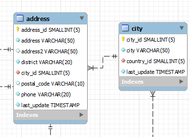
address.city_id has been defined as a foreign key referencing the city.city_id field. Drop the countrytable onto the canvas and immediately you should see the relationship between the country table and the city table. (To view all the relationships in the sakiladatabase, see Figure 9.29, “The sakila Database EER Diagram”.)Properties window, as the next figure shows. While a table is selected, you can use the Properties window to change a table's properties. For example, entering #FF0000 for the color value will change the color accent to red.
Model Navigatorpanel. This panel, the uppermost panel on the left side of the page, gives a bird's eye view of the entire EER canvas.MySQL Workbench Models file (mwb extension) by choosing from the menu or by using the keyboard command Control+ S.
Using the Default Schema
When you first open MySQL Workbench a default schema, mydb appears as the leftmost tab of the Physical Schemas section of MySQL Workbench as the following figure shows. You can begin designing a database by using this default schema.
To change the name of the default schema, double-click the schema tab. This opens a schema editor window docked at the bottom of the application. To undock or redock this window, double-click anywhere in the editor title bar.
To rename the schema, use the field labeled Name. After you have renamed the schema, a lightning bolt icon appears right aligned in the Name field, indicating that other changes are pending. Click the Comments field and a dialog box opens asking if you wish to rename all schema occurrences. Clicking ensures that your changes are propagated throughout the application. Add comments to the database and change the collation if you wish. Close the schema editor by clicking the button.
mydb appears as the leftmost tab of the Physical Schemas section of MySQL Workbench as the following figure shows. You can begin designing a database by using this default schema.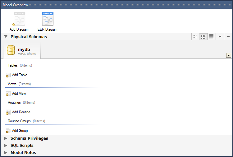
Creating a New Table
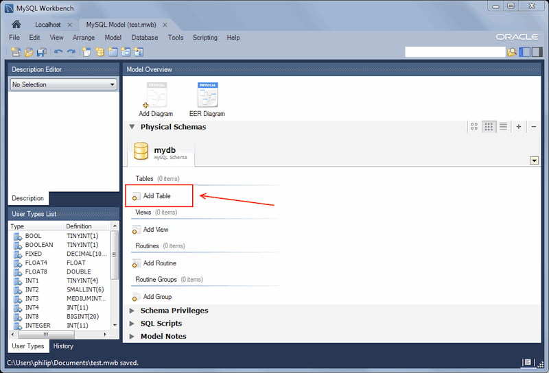
Create a new table by double-clicking the Add Table icon in the Physical Schemas panel, as the next figure shows. This action opens the table editor docked at the bottom of the application. You can undock or dock this editor in exactly the same way as the schema editor window.
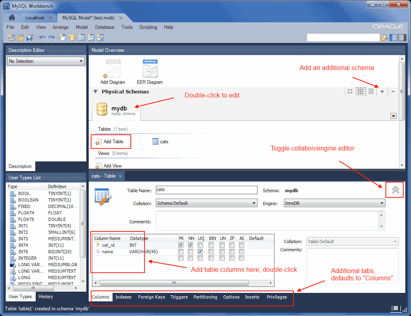
Initially, the table name defaults to 'table1' in the table editor. The following figure describes the available actions.
In the previous example, columns were added using the Columns tab. Clicking an empty row will add a new column, and clicking an existing column starts edit mode. Click the Tab key to move to the next column and set the column's data type.
Altering the table by adding indexes or other features is also possible using the table editor by clicking each tab within the table editor...
Creating Other Schema Objects
Additional objects such as views or routines can be added in the same way as tables.
Objects are listed under the Catalog palette on the right. To view these schema objects, select the Catalog tab in the middle palette on the right. View all the objects by clicking the button to the left of the schema name.
Save your changes to a MySQL Workbench Models file (mwb extension) by choosing from the menu or by using the keyboard commandControl+S.
MySQL Workbench Models file (mwb extension) by choosing from the menu or by using the keyboard commandControl+S.
Documenting the sakila Database
This chapter demonstrates the capabilities of MySQL Workbench as a documentation tool by using the sakila database, which is a database sample provided by MySQL. You can find this database sample, and others, by visiting thehttp://dev.mysql.com/doc/ page, selecting the menu, and then locating the Example Databases section.
An EER diagram provides a quick overview and understanding of a database. Rather than reading through table definition statements, a quick glance at an EER diagram indicates how tables are related.
You can also see how tables are related; what the foreign keys are and what the nature of the relationship is.
sakila database, which is a database sample provided by MySQL. You can find this database sample, and others, by visiting thehttp://dev.mysql.com/doc/ page, selecting the menu, and then locating the Example Databases section.A PNG File of the sakila Database
Find following an EER diagram showing the tables in the sakila database. The following figure shows the output that was created using the , , menu item.
The object notation style used in Figure 9.29, “The sakila Database EER Diagram” is Workbench (PKs only). This notation shows only primary keys and no other columns, which is especially useful where space is at a premium. The relationship notation is the default, Crow's Foot.
As the connection lines show, each table is related to at least one other table in the database (with the exception of the film_text table). Some tables have two foreign keys that relate to the same table. For example the film table has two foreign keys that relate to the language table, namelyfk_film_language_original and fk_film_language. Where more than one relationship exists between two tables, the connection lines run concurrently.
Identifying and non-identifying relationships are indicated by solid and broken lines respectively. For example, the foreign key category_id is part of the primary key in the film_category table so its relationship to the category table is drawn with a solid line. On the other hand, in the city table, the foreign key, country_id, is not part of the primary key so the connection uses a broken line...
Regard's
Muhammad Waseem Mayo
+923007396305
Find following an EER diagram showing the tables in the
sakila database. The following figure shows the output that was created using the , , menu item.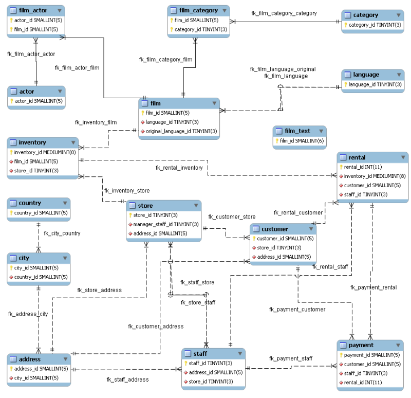
The object notation style used in Figure 9.29, “The sakila Database EER Diagram” is
Workbench (PKs only). This notation shows only primary keys and no other columns, which is especially useful where space is at a premium. The relationship notation is the default, Crow's Foot.
As the connection lines show, each table is related to at least one other table in the database (with the exception of the
film_text table). Some tables have two foreign keys that relate to the same table. For example the film table has two foreign keys that relate to the language table, namelyfk_film_language_original and fk_film_language. Where more than one relationship exists between two tables, the connection lines run concurrently.
Identifying and non-identifying relationships are indicated by solid and broken lines respectively. For example, the foreign key
category_id is part of the primary key in the film_category table so its relationship to the category table is drawn with a solid line. On the other hand, in the city table, the foreign key, country_id, is not part of the primary key so the connection uses a broken line...
Regard's
Muhammad Waseem Mayo
+923007396305
Muhammad Waseem Mayo
+923007396305


Excellent Blog, I like your blog and It is very informative. Thank you
ReplyDeletePHP
Scripting Language